Overview
The goal coordinate system defines a two-dimensional spatial reference centered on the goal mouth.It is primarily used to represent shot locations and shot trajectories relative to the goal. The coordinate system simplifies spatial analysis by normalizing the goal area into a consistent frame of reference.
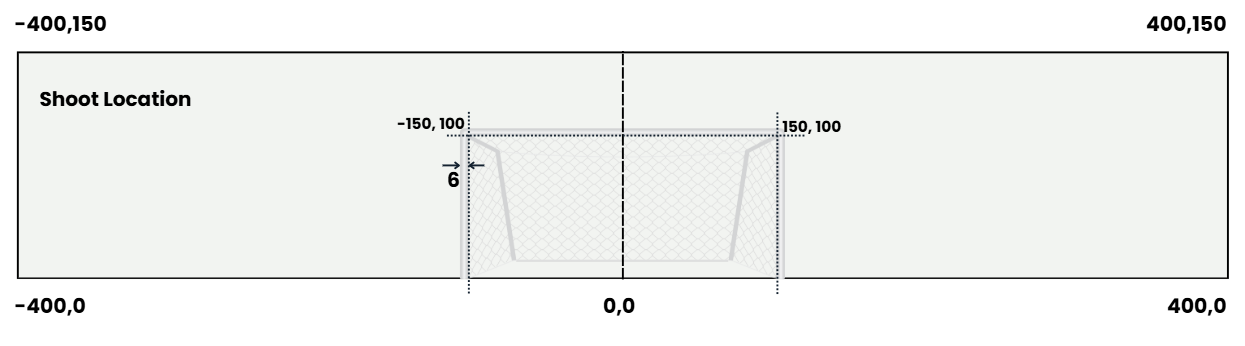
Coordinate Origin
The origin point of the system is located at:(0,0). This point represents the center of the goal line. All shot locations are measured relative to this point.| Axis | Direction | Meaning |
|---|---|---|
| X-axis | Horizontal | Left and right relative to the goal center |
| Y-axis | Vertical | Distance away from the goal line |
Horizontal Range (X Axis)
The X-axis describes the horizontal position relative to the center of the goal.| Coordinate | Description |
|---|---|
-400 | Far left of the shot analysis zone |
0 | Center of the goal |
400 | Far right of the shot analysis zone |
| Goal Post | Coordinate |
|---|---|
| Left Post | (-150,100) |
| Right Post | (150,100) |
Vertical Range (Y Axis)
The Y-axis represents the distance from the goal line moving outward toward the field.| Coordinate | Description |
|---|---|
0 | Goal line |
100 | Goal mouth depth reference |
150 | Maximum vertical analysis range |
Goal Dimensions
The goal mouth is represented using the following coordinates:| Element | Coordinate |
|---|---|
| Left Goal Post | (-150,100) |
| Right Goal Post | (150,100) |
| Goal Center | (0,100) |
Goal Depth
The goal depth is represented by the distance between: Y = 100 and the back of the goal structure. This area represents the goal frame and net region.Shot Analysis Zone
The entire shot analysis frame extends across the following boundaries:| Boundary | Coordinate |
|---|---|
| Left Limit | -400 |
| Right Limit | 400 |
| Bottom Limit | 0 |
| Top Limit | 150 |
- shots taken from wide angles
- long distance attempts
- central shots
- shots from inside the penalty area
Coordinate Interpretation
Examples of shot locations:| Shot Location | Interpretation |
|---|---|
(0,120) | Central shot toward the middle of the goal |
(-120,110) | Shot aimed toward the left side of the goal |
(140,105) | Shot aimed near the right post |
(0,30) | Shot taken very close to the goal line |
Symmetry
The coordinate system is symmetrical around the center line: X = 0 This ensures that:- left side shots use negative X values
- right side shots use positive X values
Visualization Purpose
The 2D goal coordinate system is used for:- shot location plotting
- expected goals (xG) modeling
- goalkeeper positioning analysis
- shooting heatmaps